Compressed Air System Diagram
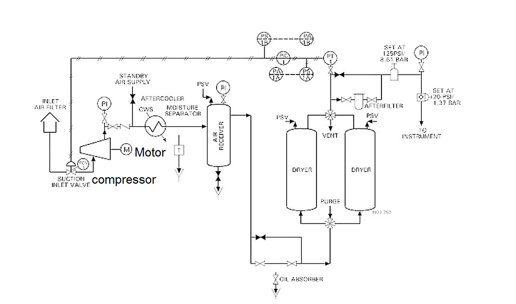
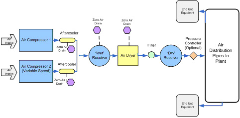
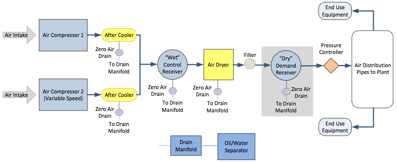
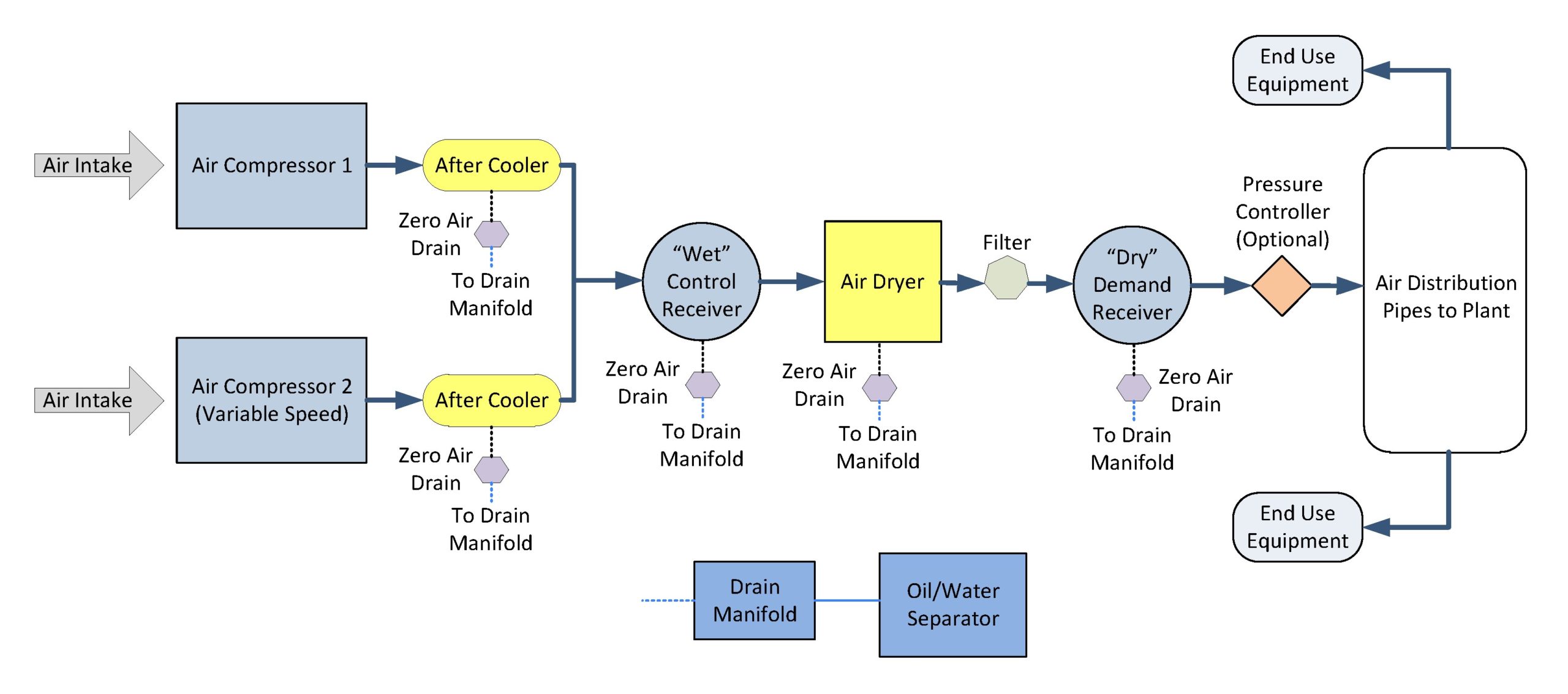
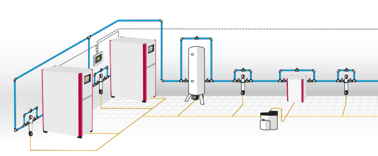
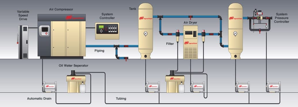
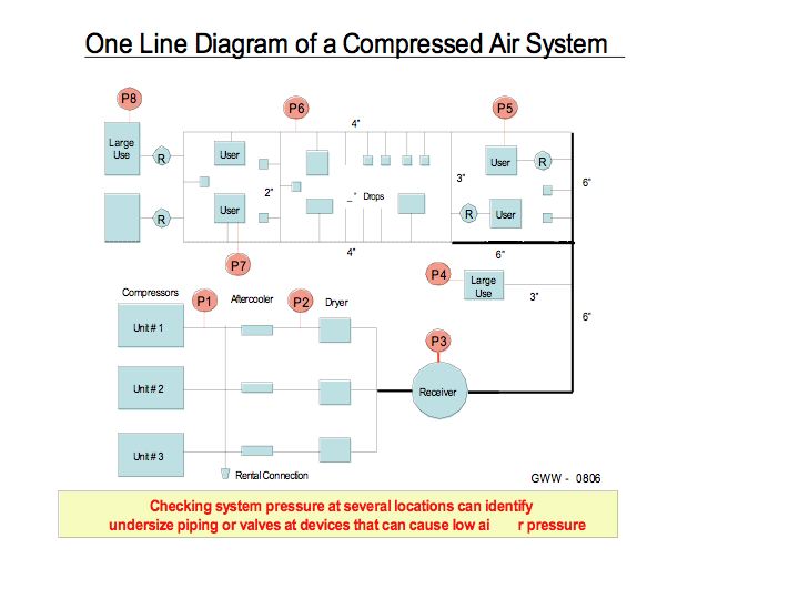
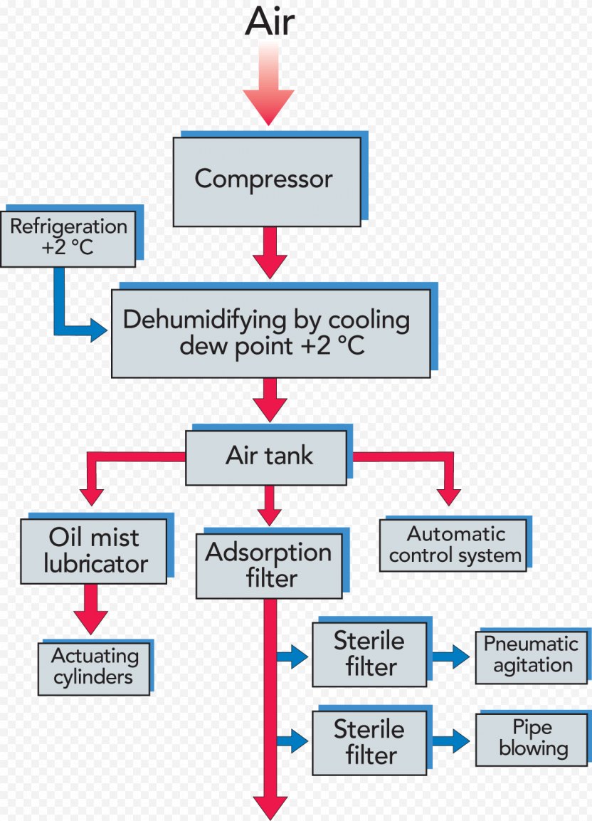
Compressed air system diagram. Compressed air systems consist of a supply side and a demand side. Your compressed air storage system consists of all the compressed-air containing vessels in your compressed air system. Optimization of an Industrial Air Compressor System Compressed air usage storage leakage and.
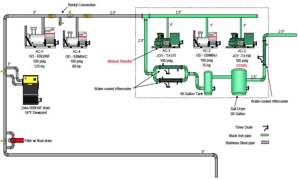
Compressed Air System Standard Piping Diagram Author. Know what equipment you have and know what is happening in your system. The air receiver tank typically makes up the bulk of total storage capacity.
When the air is exhausted the return spring in the brake chamber returns the diaphragm and pushrod to the released position. Sufficient storage is critical and represents available energy that can be released or replenished at any time as required. When youve completed the design save your project by creating an account.
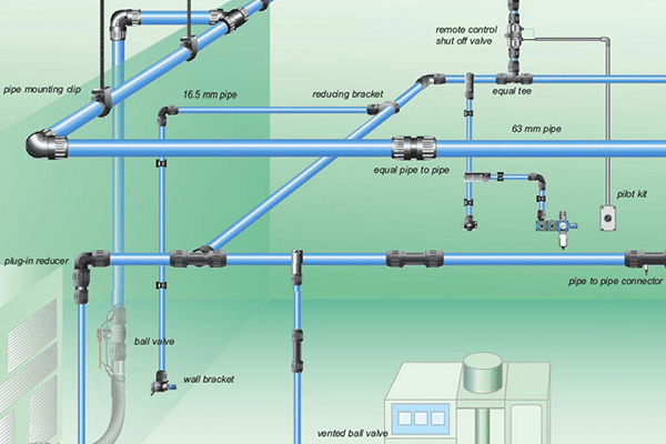
Our drag-and-drop features give you complete control over your design. We also recommend that you have an aftercooler fitted with your piping system which will remove at least 60. The inlet and discharge outlet must be designed so that they allow smooth flow of air over the entire system.
1 psi 0069 bar 0070 kgcm2. Goal of an Efficient Compressed Air System The primary goal of a compressed air system is to deliver a reliable supply of clean. 1 cfm 17 m3h 0028 m3min.
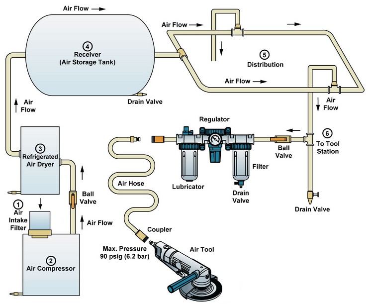
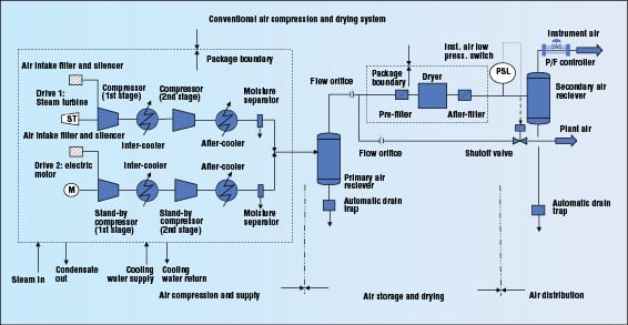
Multiple air users should not be connected to the same drop each drop should be used for a. Compressed Air System Compressor Schematic and Process41 Figure 11. The compressor produces compressed air at the required pressure.
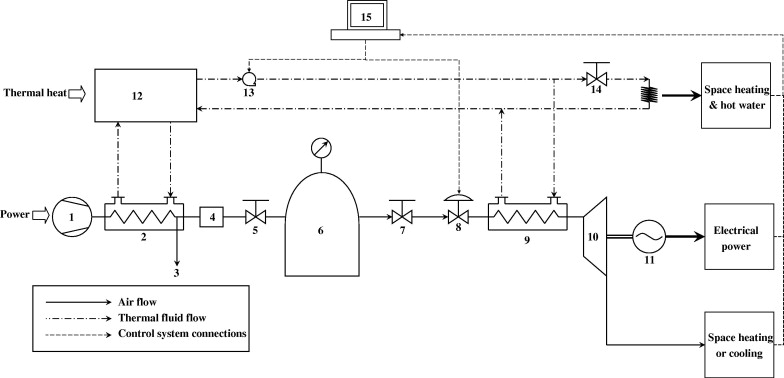
Compressed air system can save energy reduce maintenance decrease downtime increase production throughput and improve product quality. Download scientific diagram Schematic Diagram of the Compressed Air System from publication.
Your compressed air storage system consists of all the compressed-air containing vessels in your compressed air system.
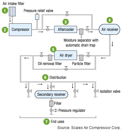
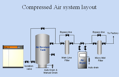
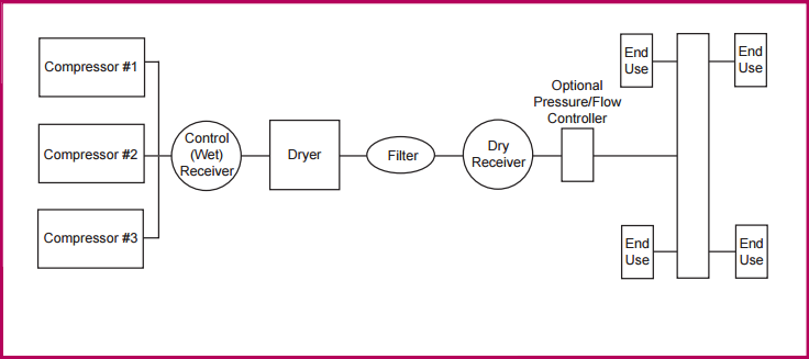
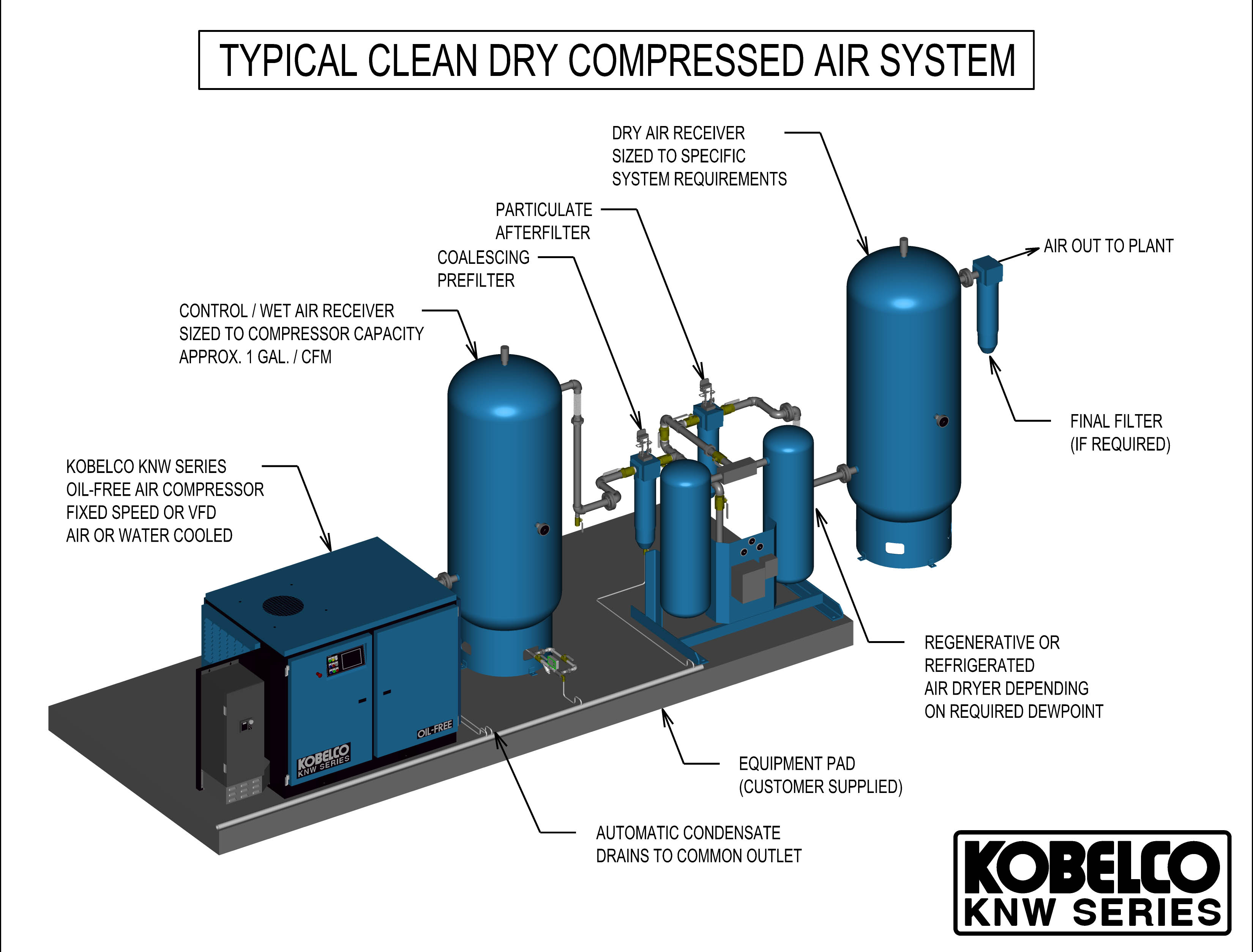
Simplified block diagram of a compressed air system. Air line drops to the six machines from the 3 main in the ceiling were 40 long ½ size hydraulic hose. And the receivers should be sized based on the CFM of the compressors. This helps because water is heavier than air and drops to the bottom of the tank. Compressed air consuming system. 1 cfm 17 m3h 0028 m3min. To deliver compressed air to where it is needed. A larger compressed air net- work can be divided into four main parts. However designing a compressed air system is more difficult than you might imagine the compressed air has to be delivered with sufficient volume good enough quality and enough pressure to power the components that require compressed air.
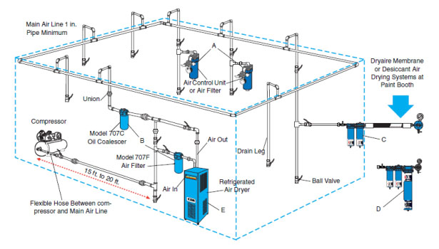
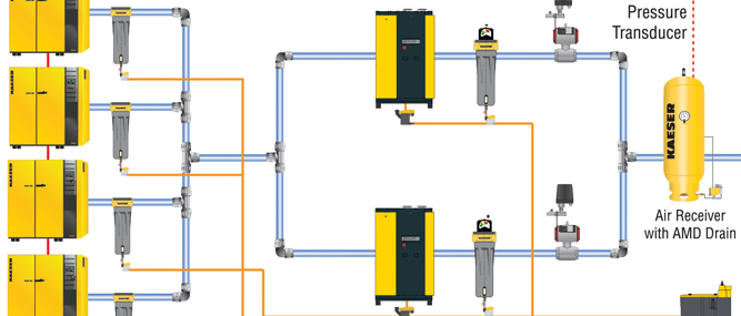
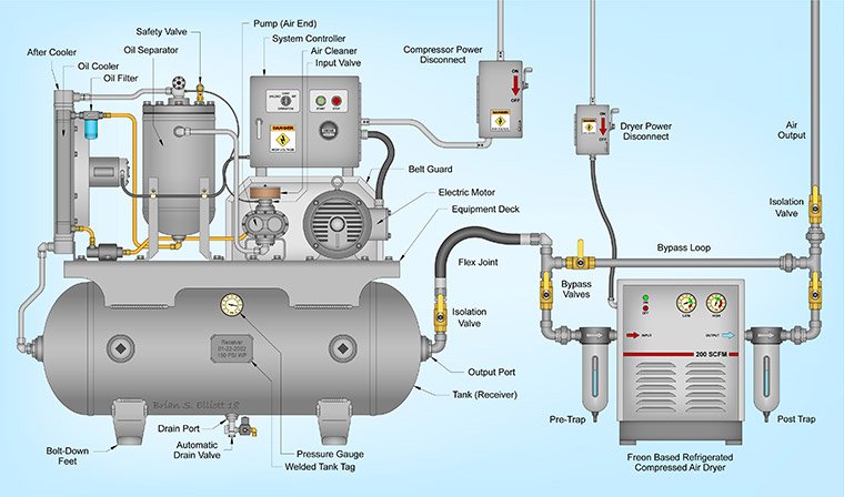
Department of Veterans Affairs Office of Acquisition Logistics and Construction Office of Construction and Facilities Management Office of Facilities Planning Facilities Standards Service Subject. The compressor produces compressed air at the required pressure. The demand side includes distribution and end-use equipment. Compressed Air System Standard Piping Diagram Author. The fresh air intake ows into a lter before entering the compressor. The purpose of compressed air piping systems is simple. 34 Compressed Air System Components Compressed air systems consist of following major components.















Post a Comment for "Compressed Air System Diagram"